Course Notes for VE370 (Introduction to Computer Organizations) | FA2020 @UM-SJTU JI, Shanghai Jiao Tong University.
To run the .s file direclty through bash, use
spim -bare
read ""
run
REMEMBER: 2’s complement
Chapter 1
Performance
To run the .s file direclty through bash, use
spim -bare
read ""
run
REMEMBER: 2’s complement
Chapter 1
Performance
-
-
ISA: Instruction Set Architecture
-
Instruction count: IC (由program, ISA, complier 决定)
-
Clock Cycle per Instruction: CPI
-
Clock Cycles = IC * CPI
momorize the equation
GHz =
Chapter 2
**Operation and Operands **

# c language
# need preprocessor
gcc -E test.c > test.i

gcc -S test.s # obtain test.s
gcc -c test.c # obtain test.o, which is machine code to read $ hexdump text.o
/*or*/
hexdump -C test.c # to show ASCII
gcc test.o -o test # obtain executable machine code test
# so gcc could followed by test.c or test.o
- Instruction Set
- RISC: reduced instruction set computer
- CISC: complex instruction set computer
MIPS Instruction Set
Design Principle
- Simplicity favors regularity.
- Smaller is faster
- Make the common case faster
Register Operands
MIPS architecture has a 32*32-bit register file
$zero: constant 0 (reg 0, also written as 0)
$at: Assembler Temporary (reg 1, or 1)
$v0, v1: result values (reg’s 2 and 3, or 2 and 3); use value for function result
$a0 – a3: arguments (reg’s 4 – 7, or 4 - 7)
$t0 – t7: temporaries (reg’s 8 – 15, or 8 - 15); can be overwritten by callee
$s0 – s7: saved (reg’s 16 – 23, or 16 - 23); be saved/restored by callee
$t8, t9: temporaries (reg’s 24 and 25, or 24 and 25)
$k0, k1: reserved for OS kernel (reg’s 26 and 27, 26/27)$gp: global pointer for static data (reg 28, or 28)
$sp: stack pointer (reg 29, or 29)
$fp: frame pointer (reg 30, or 30)
$ra: return address (reg 31, or $31)
lw rt, offset(rs)# offset should be 4*(an integer) offset: a 16-bits 2's complement number


## Byte/Halfword Operations R[rt] = Mem[R[rs] + signExtensionOffest] 为32bits与16bits相加##
lb rt, offset(rs) # offset could be any integer (-2 is okey)
lh rt, offset(rs # repeat the sign bit

lbu rt, offset(rs) # for unsigned byte;
lhu rt, offset(rs) # repeat zero

sb rt, offset(rs)
sh rt, offset(rs)
Memory Operands
-
mainly for composite data (arrays, structures, dynamic data)
-
steps
lw: from memory into registers- perfrom arithmetic operations with registers
sw: from register back to memory
-
Byte addressable - each address identifies a 8-bit byte
-
organized in word
-
Big/little Endian: MIPS is big Endian

g = h + A[8]
h in $s2, base address of A in $s3
load word
from the content in register ($s3), the content + offset (32), is the address of the content need to be loaded.
The content in the address ( Reg[$s3]) + offset (32)) is loaded in $t0
$t0 load in the content in this address. Content: A[8]

Store Word
lw $t0, 32($s3)
add $t0, $s2, $t0
sw $t0, 48($s3)
Store the content in $t0, into the content of the address (content in $s3 + 48)

-
difference between
lbandlbulb: load byte; R[rt] = SignExt(M[R[rs]+SignExtImm])lbu: load byte unsigned; R[rt] = {24b'0,M[R[rs]+SignExtImm] (7:0)}
Immediate Operands (constant)
sll by i bits = multiply by
srl by i bits = divides by (unsigned only)
load 32-bits constant
lui rt, constant- copies 16-bit constant to left 16 bits of rt
- clear right 16-bits of rt to 0
ori $t0, $t0, 0x....$t1 = $t2| ZeroExtImm
# load 0x56781234 to register $s3
lui $s3, 0x5678
ori $s3, $s3, 0x1234
For the number stored in a byte if its value is larger than (10000000) or(80)hex. If we want to load its original value to a new register, we need to use lbu. If we use lb at this time, the value stored in the new register will be negative.
If/For
no blt, bge, ble, bgt
beq, bne common; combined with slt, slti, sltiu


Byte/Halfword Operations
# i.e. load in byte 0xFA
/*Signed, with sign extension*/
	lb rt, offset(rs)		# offset could be any integer;in rt 0xFFFFFFFA
	lh rt, offset(rs)
/*Unsigned, with zero extension*/
	lbu rt, offset(rs)		# offset could be any integer; in rt 0x000000FA
	lhu rt, offset(rs)
有时候要注意offset是否要乘4,如果array是存储的bytes而不是words,则不需要乘4
Assembly Language
Example.c
int add_a_and_b(int a, int b) {
   return a + b;
}

int main() {
   return add_a_and_b(2, 3);
}
转化为汇编语言
$ gcc -S example.c
**arm! but not mips **
example.s
_add_a_and_b: # 并不是标准命令
   push   %ebx
   mov    %eax, [%esp+8]
   mov    %ebx, [%esp+12]
   add    %eax, %ebx
   pop    %ebx # pop会将ESP寄存器中地址加4
   ret  # 当前函数frame被回收

_main:
   push   3  # push: CPU指令,将运算子放入stack,即3写入main这个frame
   push   2 # push会将ESP寄存器中地址减4
   call   _add_a_and_b # call:调用函数
   add    %esp, 8
   ret
从_main开始执行,在stack上为main建立一个frame(帧),stack所指向的地址写入ESP寄存器。数据若要写入main这个frame,则写在ESP寄存器所保存的地址。stack:从高位向地位发展。ESP中地址减去四个字节(int)后,新地址写入ESP
Chapter 3
Function
program stored in memory , instructions represented in binary, like data. Each instruction is stored as a word in PC, so 0:0, 4:100, 8: 1000, all the instruction will be ended with 2’b0.
program counter
(PC) (instruction address register)
- address of the instruction is sotred in PC
- 32 bits register
- a special register in CPU (not same as the registers in register file)


function calling
Similarly, in the execution of a procedure, the program must follow these six steps:
- Put parameters in a place where the procedure can access them.
- Transfer control to the procedure.
- Acquire the storage resources needed for the procedure.
- Perform the desired task.
- Put the result value in a place where the calling program can access it.
- Return control to the point of origin, since a procedure can be called from several points in a program.
Function call instructions
-
Function call operation: jump-and-link instruction
jal FunctionLabel(J-type)An instruction that jumps to an address and simultaneously saves the address of the following instruction in a register ($ra in MIPS).
- $ra = PC+4 (the address of following instruction)
- PC = Addr(function label)
-
Function return operation: jump register
jr $ra(R-type)- PC = $ra; Copies $ra to program counter
-
return address
A link to the calling site that allows a procedure to return to the proper address;
in MIPS it is stored in register $ra.
-
caller: The program that instigates a procedure and provides the necessary parameter values.
-
Callee: A procedure that executes a series of stored instructions based on parameters provided by the caller and then returns control to the caller.
-
stack pointer ($sp)
-
pointing to the top of the stack
- By mean top, not mean when adding more items, the address of $sp would not become larger, but it should be subtracion.
-
frame pointer ($fp)
a frame pointer offers a stable base register within a procedure for local memory-references. as $sp might change
leaf function
Eg1: see swap
function that don’t call other functions
addi $sp, $sp, -12 # create spaces in stack
sw $t1, 8($sp) # store data on stack
sw $t0, 4($sp) # actually, no need to operate on $t0 and $t1
sw $s0, 0($sp)
....

lw $s0, 0($sp) # restore data from stack
lw $t0, 4($sp)
lw $t1, 8($sp)
addi $sp, $sp, 12 # destroy spaces on stack
jr $ra # return from function

Non-leaf funciton
Eg2: see sort
function that calls other functions
For nested call, caller need to save on the stack
-
its return address
-
any arguments and temporaries needed after the call

int fact (int n) {
  if (n < 1) return f;
  else return n * fact(n - 1)
}
argument n in $a0, result in $v0
fact:
		addi $sp, $sp, -8
		sw $ra, 4($sp)
		sw $a0, 0($sp)
		slti $t0, $a0, 1
		beq $t0, $zero, L1 # the label tells where to go, such that L1 should have the address
		addi $v0, $zero, 1
		addi $sp, $sp, 8
		jr $ra
L1:
		addi $a0, $a0, -1
		jal fact
		lw $a0, 0($sp)
		lw $ra, 4($sp)
		addi $sp, $sp, 8
		mul $v0, $a0, $v0
		jr $ra
Function Calling Convention
do not follow convention not mean syntax error, but highly likely to create error
when to apply
-
immediatly before the function is called
- pass arguments to $a0 - $a3 (more arguments on stack, addressable via $fp)
- save register that should be saved by caller ( i.e. $a0 - $a3 non-leaf function)
jal
-
in function, but before it starts executing
- allocate memory of frame’s size (moving $sp downwards)
- Save registers that should be saved by the function in the frame, before they are overwritten ($s0-$s7 (if to be used), $fp (if used), $ra (non- leaf function))
- Establish $fp (if desired), $fp = $sp + frame’s size - 4
-
immediatly before the funtion finishes
- if necessary, place the function result to $v0, $v1
- Restore registers saved by the function (pop from frame)
- destroy stack frame (by moving $sp upwards)
jr $ra

Example
When translate from C to assembly language
- Allocate registers to program variables.
- Produce code for the body of the procedure.
- Preserve registers across the procedure invocation.
swap
void swap(int v[], int k) {
	int temp;
	temp = v[k];
  v[k] = v[k+1];
  v[k+1] = temp;
}
1. program argument: `$a0, $a1 -> v, k` temporary variable: `$t0 -> temp`
-
/*procedure body*/
swap: sll $t1, $a1, 2 # $t1 = k * 4
      add $t1, $a0, $t1 # t1 = v + k * 4, the address of v[k]

      lw $t0, 0($t1) # $t1 (temp) = v[k]; load the content in address 0($t1) to the content oof $t0
      lw $t2, 4($t1) # $t2 = v[k+1];

      sw $t2, 0($t1) # v[k] = v[k+1]; store the content in $t2 to thr content in address 0($t1)
      sw $t0, 4($t1) # v[k+1] = temp;
/*procedure return*/
      jr $ra
sort
void sort (int v[], int n) {
  int i, j;
  for (i = 0; i < n; i += 1) {
  	for (j = i – 1; j >= 0 && v[j] > v[j + 1]; j -= 1) {
      swap(v,j);
  	}
  }
}
Problem: sort needs the value in $a0 and $a1, swap need to have the parameters placed in those same registers.
v in $a0, n in $a1, i in $s0, j in $s1
sort:
		addi $sp, $sp, -20
		sw $ra, 16($sp)
		sw $s3, 12($sp)
		sw $s2, 8($sp)
		sw $s1, 4($sp)
		sw $s0, 0($sp)
		add $s2, $a0, $zero	# $s2 = BA of v
		add $s3, $a1, $zero	# s3 = n
		add $s0, $zero, $zero	# i = 0
for1tst:
		slt $t0, $s0, $s3
		beq $t0, $zer0, exit1 # when i >= n, exit the first loop
		addi $s1, $s0, -1 # j = i - 1
for2tst:
		slt $t0, $s1, 0
		bne $t0, $zero, exit2 # when j < 0 exit the second loop
		sll $t1, $s1, 2 # $t1 = j*4
		add $t2, $t1, $s2 # t2: the address of v[j]; v + j * 4
		lw $t3, 0($t2) # v[j]
		lw $t4, 4($t2) # v[j + 1]
		sll $t0, $t4, $t3
		beq $t0, $zero, exit2 # v[j] < v[j + 1]
		add $a0, $s2, $zero # prepare for the paramete needed for next function call swap
		add $a1, $s1, $zero
		jal swap
		addi $s1, $s1, -1
		j for2tst
exit2:
		addi $s0, $s0, 1 #i+=1
		j for1tst
exit1:
	 lw $s0, 0($sp)
	 lw $s1, 4($sp)
	 lw $s2, 8($sp)
	 lw $s3, 12($sp)
	 lw $ra, 16($sp)
	 addi $sp, $sp, 12
	 jr $ra 							# return to calling routine
fib
int fib(int n) {
  if (n < 3)
    return 1;
  else
    return fib(n-1) + fib(n-2);
}
fib:
	addi 	$sp, $sp, -12
	sw		$s0, 8($sp)
	sw 		$a0, 4($sp)
	sw		$ra, 0($sp)
	slti	$t0, $a0, 3
	beq		$t0, $zero, else
	# lw		$ra, 0($sp) unnecessary load here
	# lw		$a0, 4($sp)
	addi	$sp, $sp, 12
	addi	$v0, $zero, 1
	jr		$ra

else:
	lw		$ra, 0($sp)
	lw		$a0, 4($sp)
	addi 	$a0, $a0, -1
	jal	 	fib

	add	 	$s0, $v0, $zero	# we need $s0 to store the value so adjust the stack for 3 items
	sw 		$a0, 4($sp)
	sw		$ra, 0($sp)
	addi 	$a0, $a0, -2
	jal 	fib
	addi 	$t1, $v0, 0
	lw		$ra, 0($sp)
	lw		$a0, 4($sp)
	addi	$sp, $sp, 8
	add		$v0, $t1, $t0
	jr 		$ra
# VE370 2020FA RC Week 3
# Class exercise: fib
# Author: Li Shi

# Important note:
#   This program is written in Linux, and executed by
#     1. spim -bare
#     2. (spim) read "fib.s"
#     3. (spim) run
#   You may need to modify this program to execute in PCSpim.

.text

main:
  addi  $a0,  $0,   8
  jal   fib                 # Call fib(8)
  add   $t0,  $t0,  $0      # Delay
  add   $t0,  $t0,  $0      # Delay
  addi  $a0,  $v0,  0       # Print fib(8)
  addi  $v0,  $0,   1
  syscall
  addi  $v0,  $0,   10      # System call 10 (exit)
  syscall                   # Exit

fib:
  addi  $sp,  $sp,  -12     # Allocate the stack frame
  sw    $ra,  8($sp)
  sw    $a0,  4($sp)
  sw    $s0,  0($sp)        # We will use $s0 later
  slti  $t0,  $a0,  3       # Test for n < 3
  beq   $t0,  $0,   elseBlock
  addi  $v0,  $0,   1       # return 1
  addi  $sp,  $sp,  12
  jr    $ra
  add   $t0,  $t0,  $0      # Delay

elseBlock:
  addi  $a0,  $a0,  -1
  jal   fib                 # fib(n-1)
  add   $t0,  $t0,  $0      # Delay
  add   $t0,  $t0,  $0      # Delay
  addi  $s0,  $v0,  0       # Q: What is $s0 used for?
  addi  $a0,  $a0,  -1
  jal   fib                 # fib(n-2)
  add   $t0,  $t0,  $0      # Delay
  add   $t0,  $t0,  $0      # Delay
  add   $v0,  $v0,  $s0     # return fib(n-1)+fib(n-2)
  lw    $s0,  0($sp)
  add   $t0,  $t0,  $0      # Delay
  add   $t0,  $t0,  $0      # Delay
  lw    $a0,  4($sp)
  add   $t0,  $t0,  $0      # Delay
  add   $t0,  $t0,  $0      # Delay
  lw    $ra,  8($sp)
  add   $t0,  $t0,  $0      # Delay
  add   $t0,  $t0,  $0      # Delay
  addi  $sp,  $sp,  12      # Pop the stack
  add   $t0,  $t0,  $0      # Delay
  add   $t0,  $t0,  $0      # Delay
  jr    $ra
  add   $t0,  $t0,  $0      # Delay
Template
- if ($s0 < $s1) { ... } else { ... }
      slt $t0, $s0, $s1
      beq $t0, $zero, else
      ....
      j elseExit ## remember to jump out when finish if
else: ....
elseExit:
- for ($t0 = 0; $t0 < $a1; $t0++) { ... }
Loop:
		add $t0, $zero, $zero
		slt $t1, $t0, $a1
		beq $t1, $zero, exit
		...
		addi $t0, $t0, 1
		j Loop
exit:
Translation and Startup

Complier
tansform the C program into an assembly language program (a symbolic form of waht the machine understands)
assembler
To produce the binary version of each instruction in the assembly language program, the assembler must determine the addresses corresponding to all labels. Assemblers keep track of labels used in branches and data transfer instructions in a symbol table. As you might expect, the table contains pairs of symbols and addresses.

producing an object module
Example

- In the object file:
the instructions in assembly language just to make the example understandable; in reality, the instructions would be numbers.
Note that the address and symbols that must be updated in the link process is higlighted:
			1. the instructions that refer to the address of procedures $A$ and $B$

			2. the instructions that refers to the data word $X$ and $Y$

linker
Also called link editor. A systems program that combines independently assembled machine language programs and resolves all undefined labels into an executable file.
-
merge segments
-
resolve labels (determine their address)
-
patch location-dependent and external reference
example of linked objects
Object is already machine language, but no memory has been traslated (the translator do not know about)
the text segment starts at address 40 0000hex and the data segment at 1000 0000hex.

- The jals are easy because they use pseudodirect addressing. The jal at address 40 0004hex gets 40 0100hex (the address of procedure B) in its address field, and the jal at 40 0104hex gets 40 0000hex (the address of procedure A) in its address field.
- The load and store addresses are harder because they are relative to a base register. This example uses the global pointer as the base register. Figure 2.13 shows that $gp is initialized to 1000 8000hex. To get the address 1000 0000hex (the address of word X), we place 8000hex in the address field of lw at address 40 0000hex (Because it is 2’s complement). Similarly, we place 7980hex in the address field of sw at address 40 0100hex to get the address 1000 0020hex (the address of word Y).
- also output an object file
Loader
- Reads the executable file header to determine size of the text and data segments.
- Creates an address space large enough for the text and data.
- Copies the instructions and data from the executable file into memory.
- Copies the parameters (if any) to the main program onto the stack.
- Initializes the machine registers and sets the stack pointer to the first free location. ($sp, $gp, $fp)
- Jumps to a start-up routine.
- copies the parameters into the argument registers ($a0...) and calls the main routine
- When the main routine returns, the start-up routine terminates the program with an exit system call
之前讲了static link, 即before the program is run 1. the library routines become part of the executable file 2. it loads all routines in the library that are called anywhere executable
so -> dynamically linked libraries (DLLs): Library routines that are linked to a program during execution.
Dynamic Linking
dll: dynamic linking library

Topic 4
Instructoin coding, how the assembler and linker transform into machine code.
MIPS instruction -> 32 bits words, translated into binary information (machine code)
first 6 bits -> opcode always, for all three types. Based on this, CPU now what to do.
R-format
totally 32 bits, can see from the reference card 
Instruction fields
Here is the meaning of each name of the fields in MIPS instructions:
- op: Basic operation of the instruction, traditionally called the opcode.
- rs: The first register source operand.
- rt: The second register source operand.
- rd: The register destination operand. It gets the result of the operation.
- shamt: Shift amount. (Section 2.6 explains shift instructions and this term; it will not be used until then, and hence the field contains zero in this section.) only use when shift, represents the number we want to shift (0-31)
- funct: Function. This field, often called the function code, selects the specific variant of the operation in the op field.
add $t0, $s1, $s2
add: 0 (opcode)
rs: $s1 (5 -bits store the memory) 10001
rt: $s2 10010
rd: $t0 (becasue this is the register destination)01000

add and sub have the same opcode, use the different func field to distinguish between these two.
I-format
i- immediate number

rt: destination now however it could also be source (determine by read / write operation)
rs: source or base address register
constant / address: to / offset added to base address in rs
Read: source register Write: destination


sw $t0, 4($s0) # $s0->rs / $t0 -> rt
read from the register both $s0->rs $t0->rt. // no destination register needed
relative address = (LOOP-PC-4)/4. // because relative address should have a 32-bits address, so by calculation, we could use relative address (16 bits)
lui $t0, 255 # because $t0 is the destination register
| opcode | rs | rt | Immediate |
|---|---|---|---|
| 001111 | 00000 | 01000 | 0000 0000 1111 1111 |


J-format

encode full address in instruction, use 26 bits represent a 32 bits address
leave the first 4 bits of PC untouched.

Addressing in Branches and Jumps
- J-type: 6 bits for operation field and the rest of the bits for the address field.
j 10000 can be assembled into
| 2 | 10000 |
|---|---|
| 6 bits | 26 bits |
the value of the jump opcode is 2 and the jump address is 10000
- PC-relative addressing
a branch instruction would calculate: Program counter = Register + Branch address
for conditional branches: loops and statements
Decoding Machine Code
- converting hex to binary to find op fields, determine the operation

-
How to get address
- immediate addressing
- I-type
addi $s0, $s1, -1
- I-type
- register addressing
- R-type / I-type : all or some operands provided by register IDs directly
add $t0, $s0, $s1
- R-type / I-type : all or some operands provided by register IDs directly
- base addressing
- I-type: operands provided by using base address of memory location
lw $t0, 32($s0)
- I-type: operands provided by using base address of memory location
- PC-relative addressing
- Operands relative to PC, used for near branch target address = PC + 4 + offest * 4 ,
beq $s0, $s1, LESS
- Operands relative to PC, used for near branch target address = PC + 4 + offest * 4 ,
- Pseudodirect addressing
- encode full address in instruction J-type (
jandjal) target address = PC[31:28] : address * 4
- encode full address in instruction J-type (
- immediate addressing
instructions from memory & data from/into RF/memory

T05
Review of Digital Logic
who to control reading / writing? do not read / write at the same time -> control signal in RF
-
memory (access memory is slower than access RF, because of the big circuit of memory, need to decode the address)
- SRAM (Static RAM)

- DRAM

memory in MIPS
insturction memory: only read afterwards
data memory: only one address for read / write

If need write, write first
T06
Single Cycle Processor Chapter 4.1-4.4
■■ The memory-reference instructions load word (lw) and store word (sw)
■■ The arithmetic-logical instructions add, sub, AND, OR, and slt
■■ The instructions branch equal (beq) and jump (j), which we add last
PC is controled by clock signal
every instruction, needs: send the PC to the memory that contains the code and fetch the instruction from that memory / read one or two registers, using fields of the instruction to select.
state element: a memory element, such as a register or a memory
- clocking methodology: edge-triggered clocking: a clocking scheme in which ass state changes occur on a clock edge. Only state elements can store data value, any collection of combinational logic must have its inputs come from a set of state elements and its outputs written into a set of state elements. The inputs are values that were written in a previous clock cycle, while the outputs are values that can be used in a following clock cycle.
- ALUOp & funct -> ALU Control

Generate a 2-bit ALUOp (by CPI controller). With ALUOp and funct field -> ALU control

that is, using multiple levels of decoding -> reduce the size of the main control unit (opcode before)
The corresponding truth table is as follows, don’t care term all represented with X

-
instruction format
opcodebits [31:26] as Op[5:0]Two register be read
rsrt[25:21] and [20:16] (R-type, beq, store)base register for load and store
rs[25:21]offset [15:0] (beq, load, store)
destination register - load:
rt[20:16] - R-type:
rd[15:11] -> use a Mux to select -
usage of seven control lines

For R-type, will not use data memory
lw: read register from register file, ALU calculate the address, read data from data memory, store the data read back to register file

Clocking Methodology
lw load type instruction will need most time (becasuse of read from data)
beq only read from register and do some calculation, will not cost more time
sigle-cycle processor is not feasible to vary period for differerent instructions

clock cycle time for single-cycle processor will be 800ps, regardless of the instructions’ distribution
execution time is
multi-cycle CPU - FSM: each instruction takes multiple cycles to execute

still which operation will take the longest time - Instr Fetch: 200ps
However, with different distribution, multi-cycle will have different total execution time, some may be worse than single-cycle some may be worse.
T07
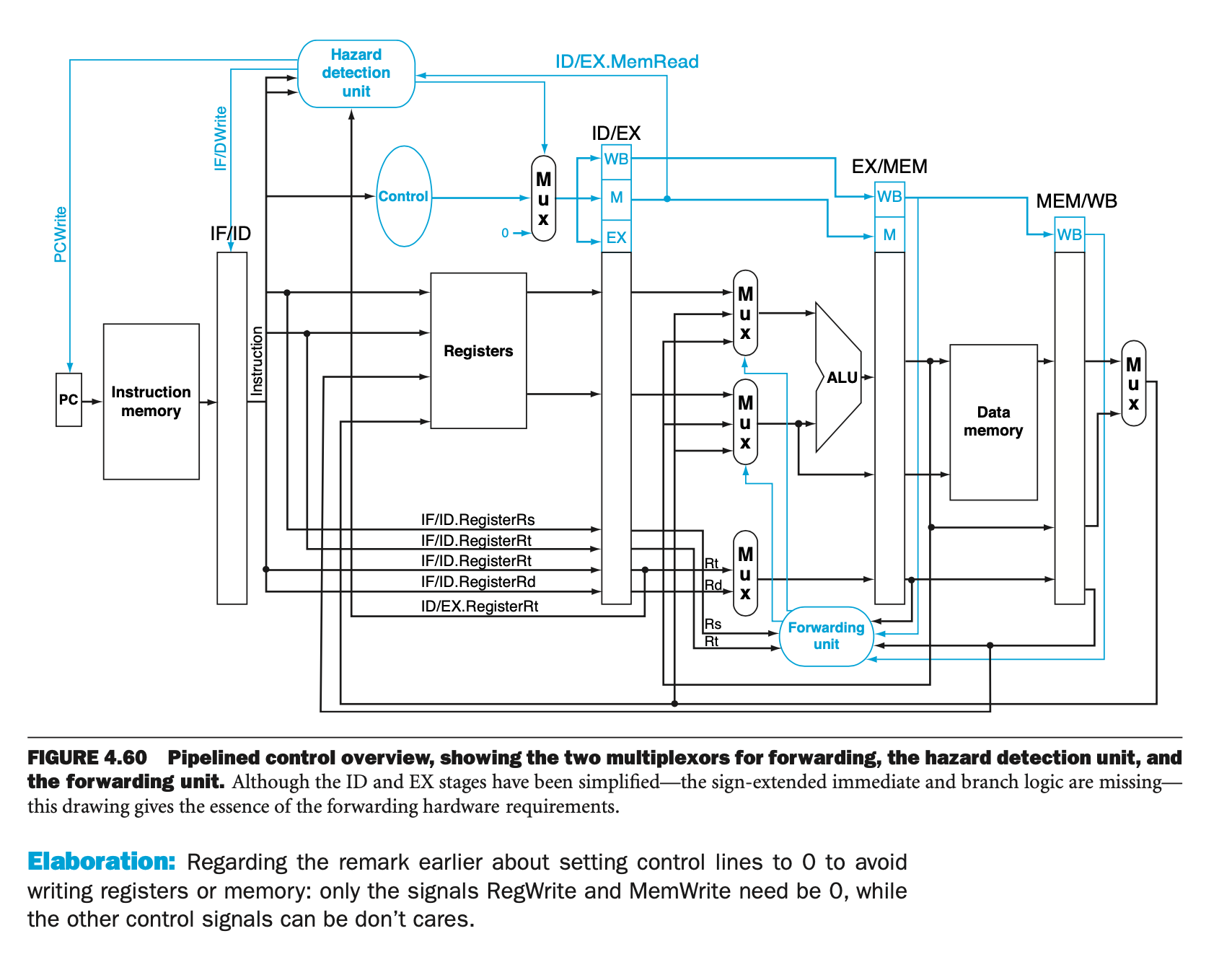
Pipelined Processor
divide the big combinational circuit into five small stages, one step per stage per cycle
- IF: Instruction fetch
- ID: Instruction decode and register file read
- EX: Execution or address calculation
- MEM: Data memory access
- WB: Write result back to register
Single-clock-cycle diagram / multi-clock-cycle diagram
Instruction-level parallism: multiple instructions exectued at the same time
execution time for each instruction does not improve (all need to execute the five stages)

T08
Data Hazards
- add stalls: nop instructions
- forwarding (bypassing) : use data before it is stored into the register

hazard notation
1a. EX/MEM.RegisterRd = ID/EX.RegisterRs
1b. EX/MEM.RegisterRd = ID/EX.RegisterRt
2a. MEM/WB.RegisterRd = ID/EX.RegisterRs
2b. MEM/WB.RegisterRd = ID/EX.RegisterRt
-
Forwarding in EX stage
we consider only the challenge of forwarding to an operation in the EX stage, which may be either an ALU operation or an effective address calculation. (instruction tries to use a register in its EX stage that an earlier instruction intends to write in its WB stage, we actually need the values as inputs to the ALU. )
EX hazard
if (EX/MEM.RegWrite  // check whether previous a WB to register file needed
 and (EX/MEM.RegisterRd ≠ 0)  // check whether we need to change the content of $zero
 and (EX/MEM.RegisterRd = ID/EX.RegisterRs)) // check whether the destination register need to use for this ALU
 ForwardA = 10

if (EX/MEM.RegWrite
 and (EX/MEM.RegisterRd ≠ 0)
 and (EX/MEM.RegisterRd = ID/EX.RegisterRt)) ForwardB = 10
Note that the EX/MEM.RegisterRd field is the register destination for either an ALU instruction (which comes from the Rd field of the instruction) or a load (which comes from the Rt field).

MEM HARZARD
if (MEM/WB.RegWrite
	and (MEM/WB.RegisterRd ≠ 0)
	and not(EX/MEM.RegWrite and (EX/MEM.RegisterRd ≠ 0))
			and (EX/MEM.RegisterRd ≠ ID/EX.RegisterRs)
	and (MEM/WB.RegisterRd = ID/EX.RegisterRs)) ForwardA = 01

if (MEM/WB.RegWrite
	and (MEM/WB.RegisterRd ≠ 0)
	and not(EX/MEM.RegWrite and (EX/MEM.RegisterRd ≠ 0))
		and (EX/MEM.RegisterRd ≠ ID/EX.RegisterRt)
	and (MEM/WB.RegisterRd = ID/EX.RegisterRt)) ForwardB = 01
To select the signed immidiate, add another MUX unit (choose from the output of forward B between signExtend)

Load use hazard detection
If value not computed when needed
$2 is needed in and instruction before it is read from data mem
 *
*

Add the stall(bubble) by
- Force control signals in ID/EX register to 0’s (the MUX) (nothing will do with this 0 control signals)
- Prevent the update of PC and IF/ID register
PCWrite=0, IF/IDWrite=0 when Hazard=1

Final Review
Pipeline
hazard detection unit and forwarding unit are seperate, such that we should not let hazard detection to control whether and which should forwrding

-
load-use hazard. insert bubbles: let control signals in ID/EX registers be zero, EX, MEM, WB stage will do nothing with these zero control signals. Registers value still exist. PC and IF/ID register’s value do not change. 会有EX的data hazard(对nop),但是ineffective,会在下一个MEM hazard的作为下个instruction的值替换
在下一个instruction为sw时,如有data hazard,为避免stall太多,加一个MemSrc来控制data mem要write的data可以直接来自MEM/WB
-
control hazard, flush the wrong instruction. When determine branch (including address calculation and whether to branch through comparator) in
- ID: IF/ID.Reg.flush
- EX: IF/ID.Reg.flush + ID.flush
- MEM: IF/ID.Reg.flush + ID.flush + EX.flush
ID.flush 和 EX.flush 是针对control signal而不是整个register都变为0
-
data hazard for branch 前一个是R type 必须stall 一个,前一个是lw必须stall 两个。再进行forwarding 到ID ex
-
exception
Cache
All data in a memory must also be present in its lower level
Overall
-
Block placement
-
block identification
- for direct map: 通过block index locate,tag只需要比对一次(index是block index)
- for n-way set associative: 通过set index locate,比较所有tag,n次(无block index 只有set index)
- for full associative:search all entries(n times) / lookup table (0 time) (无block/set index)
-
block replacement
-
write strategy
write through 比起 write back 要cheaper一些,因为check match和write data可以同时进行(saves a step for hit)
以及可以分别被应用于两个的 write allocation on miss
write allocate: allocate cache block on miss by fetching corresponding memory block; update cache block; update memory block
no write allocate: write around(write directly to memory); fetch from memory
- write through 要找到原有的先写到cache里面,再用新的覆盖掉cache里面的然后写入main memory
- write buffer: 针对write through的方法,把要写进memory的data放进buffer里面,CPU接着往下走留着buffer完成之后的工作(cache里面的和buffer一起实时更新,main里面的memory在之后由buffer更新)
- write back: keep a dirty bit. When need to replace a block with dirty bit == 1 in the cache, write the block back into main memory first
- write buffer:用于write back则是write into buffer and checking match 同时

- write through 要找到原有的先写到cache里面,再用新的覆盖掉cache里面的然后写入main memory
-
Sources of misses 3C model: Compulsory | Capacity | Conflict
Points
-
principle of locality
-
principle of memory access
- Hit time: time to access a memory, including
- whether hit/miss
- time to pass block to requestor
- miss penalty: time to fetch a block from lower level upon a miss, including
- time to access the block
- time to transfer it between levels
- time to overwrite the higher level block
- time to pass block to requestor
- Hit time: time to access a memory, including
-
block size
- larger block should reduce miss rate (spatial locality)
Difference types of cache
word offset 是针对一个block里面的word数量决定
并不是改了cache内容就dirty了!是一个block里面的数被sw/sb改掉了
all blocks in a set must be searched (tag search in parallel + extra hardware & access (hit) time )
directed mapped cache:
- byte address = word address (block address(tag + block index) + word offset) + byte offset
- cache consists of (valid bit + tag + data)
word offset由一个block里面有多少word决定 (但transfer要一个block一起transfer,于是会有hit due to spatial locality)可以用除法来表示舍弃之后几位(除以4就是舍掉最后两位,比如offset)
 、
、
N-way set associative cache: 需要set index,但access一个set中的block必须compare N次
byte address = word address (block address(tag + set index) + word offset) + byte offset
Full-associative cache
一个block可以去任意一个cache entry,comparator的数量就是cache size, no index
-
byte address = word address (block address(tag) + word offset) + byte offset
-
Average Memory Access Time (AMAT): hit time + miss rate * miss penalty
-
reduce miss penalty: early start / critical word first 可能要再看
-
increase associativity decrease miss rate (with diminishing improvement)
-
multiple caches时的
-
LRU 要keep reference bit 对于high associativity: complex and costly hardware
Virtual Memory
-
VM block is called a page, VM miss is called a page fault
-
virtual address some maps to physical address, some to disk address, through address translation
-
physical address usually smaller than virtual address
-
n to one map
-
page fault: page is not present in memory, the page must be fetched from disk
-
-
virtual address = virtual page number + page offset
- Processor always provide virtual address
- page offset: eg. 12bits -> 4K byte page size
- virtual page numebr translated into physical page number, while physical always be larger
- virtual page number used as tag when TLB hit & used as page table index when TLB miss to access page table
-
Translator - Page Table (for each program)
- Store all mapping & indexed by virtual page numbers & located in main
- page table register
-
Translation Look-aside Buffer (TLB) - fast cache of page table within CPU
- Page table -> TLB == main -> cache
- a subset of page table
- full associativity: to lower miss rate (because for small TLB, access time not a major concern)
- LRU (need to keep a reference bit) or random replacement
- physical address will be pointed by both TLB and page table
-
TLB miss: cache tag (comparison) + valid bit | Page Fault: by page table valid bit (no comparison)
- TLB miss:
- TLB is full: ref bit and dirty bit of replaced entry should be copied back to page table, but not for valid bit
- TLB miss:
-
Page write: disk write takes millions of time ! 不可以write through
- page table always write back ! (dirty bit in page table)
- write an entire page is more efficient than write a word
-
TLB and cache interaction:还要再看
- for physically addressed cache

- Virtual addr -> TLB -> provide physical address to cache (may have longer time because TLB on critical path)
 The cache is physical address, (cache index and tag are both physical )
- virtually addressed cache: 只有在cache miss的时候需要将virtual address翻译成physical address
- complications due to aliasing
- This ambiguity would allow one program to write the data without the other program being aware that the data had changed. Completely virtually addressed caches either introduce design limitations on the cache and TLB to reduce aliases or require the operating system, and possibly the user, to take steps to ensure that aliases do not occur.
- for physically addressed cache
Overall Framework

conflict miss Also called collision miss. A cache miss that occurs in a setassociative or direct mapped cache when multiple blocks compete for the same set and that are eliminated in a fully associative cache of the same size. not exist for full-associativity cache
再看一下书上的判断题/可能的多选题/page table那几个书上的题
-
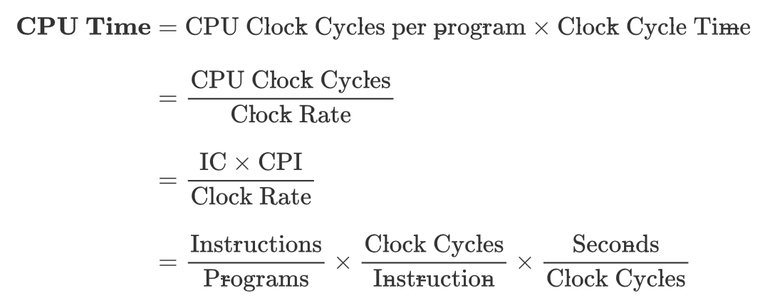
\begin{equation} \begin{aligned} \rm{\textbf{CPU Time}}&=\rm{CPU\ Clock\ Cycles\ per\ program \times Clock\ Cycle\ Time}\\[2ex] &=\frac{\rm{CPU\ Clock\ Cycles}}{\rm{Clock \ Rate}} \\[2ex] &= \frac{\rm{IC}\times \rm{CPI}}{\rm{Clock\ Rate}} \\[2ex] &= \frac{\rm{Instructions}}{\rm{Programs}} \times \frac{\rm{Clock\ Cycles}}{\rm{Instruction}} \times \frac{\rm{Seconds}}{\rm{Clock\ Cycles}} \end{aligned} \end{equation}
-
ISA: Instruction Set Architecture
-
Instruction count: IC (由program, ISA, complier 决定)
-
Clock Cycle per Instruction: CPI
-
Clock Cycles = IC * CPI
momorize the equation
GHz =
Chapter 2
**Operation and Operands **

# c language
# need preprocessor
gcc -E test.c > test.i

gcc -S test.s # obtain test.s
gcc -c test.c # obtain test.o, which is machine code to read $ hexdump text.o
/*or*/
hexdump -C test.c # to show ASCII
gcc test.o -o test # obtain executable machine code test
# so gcc could followed by test.c or test.o
- Instruction Set
- RISC: reduced instruction set computer
- CISC: complex instruction set computer
MIPS Instruction Set
Design Principle
- Simplicity favors regularity.
- Smaller is faster
- Make the common case faster
Register Operands
MIPS architecture has a 32*32-bit register file
$zero: constant 0 (reg 0, also written as 0)
$at: Assembler Temporary (reg 1, or 1)
$v0, v1: result values (reg’s 2 and 3, or 2 and 3); use value for function result
$a0 – a3: arguments (reg’s 4 – 7, or 4 - 7)
$t0 – t7: temporaries (reg’s 8 – 15, or 8 - 15); can be overwritten by callee
$s0 – s7: saved (reg’s 16 – 23, or 16 - 23); be saved/restored by callee
$t8, t9: temporaries (reg’s 24 and 25, or 24 and 25)
$k0, k1: reserved for OS kernel (reg’s 26 and 27, 26/27)$gp: global pointer for static data (reg 28, or 28)
$sp: stack pointer (reg 29, or 29)
$fp: frame pointer (reg 30, or 30)
$ra: return address (reg 31, or $31)
lw rt, offset(rs)# offset should be 4*(an integer) offset: a 16-bits 2's complement number


## Byte/Halfword Operations R[rt] = Mem[R[rs] + signExtensionOffest] 为32bits与16bits相加##
lb rt, offset(rs) # offset could be any integer (-2 is okey)
lh rt, offset(rs # repeat the sign bit

lbu rt, offset(rs) # for unsigned byte;
lhu rt, offset(rs) # repeat zero

sb rt, offset(rs)
sh rt, offset(rs)
Memory Operands
-
mainly for composite data (arrays, structures, dynamic data)
-
steps
lw: from memory into registers- perfrom arithmetic operations with registers
sw: from register back to memory
-
Byte addressable - each address identifies a 8-bit byte
-
organized in word
-
Big/little Endian: MIPS is big Endian

g = h + A[8]
h in $s2, base address of A in $s3
load word
from the content in register ($s3), the content + offset (32), is the address of the content need to be loaded.
The content in the address ( Reg[$s3]) + offset (32)) is loaded in $t0
$t0 load in the content in this address. Content: A[8]
Store Word
lw $t0, 32($s3)
add $t0, $s2, $t0
sw $t0, 48($s3)
Store the content in $t0, into the content of the address (content in $s3 + 48)

-
difference between
lbandlbulb: load byte; R[rt] = SignExt(M[R[rs]+SignExtImm])lbu: load byte unsigned; R[rt] = {24b'0,M[R[rs]+SignExtImm] (7:0)}
Immediate Operands (constant)
sll by i bits = multiply by
srl by i bits = divides by (unsigned only)
load 32-bits constant
lui rt, constant- copies 16-bit constant to left 16 bits of rt
- clear right 16-bits of rt to 0
ori $t0, $t0, 0x....$t1 = $t2| ZeroExtImm
# load 0x56781234 to register $s3
lui $s3, 0x5678
ori $s3, $s3, 0x1234
For the number stored in a byte if its value is larger than (10000000) or(80)hex. If we want to load its original value to a new register, we need to use lbu. If we use lb at this time, the value stored in the new register will be negative.
If/For
no blt, bge, ble, bgt
beq, bne common; combined with slt, slti, sltiu
Byte/Halfword Operations
# i.e. load in byte 0xFA
/*Signed, with sign extension*/
	lb rt, offset(rs)		# offset could be any integer;in rt 0xFFFFFFFA
	lh rt, offset(rs)
/*Unsigned, with zero extension*/
	lbu rt, offset(rs)		# offset could be any integer; in rt 0x000000FA
	lhu rt, offset(rs)
有时候要注意offset是否要乘4,如果array是存储的bytes而不是words,则不需要乘4
Assembly Language
Example.c
int add_a_and_b(int a, int b) {
   return a + b;
}

int main() {
   return add_a_and_b(2, 3);
}
转化为汇编语言
$ gcc -S example.c
**arm! but not mips **
example.s
_add_a_and_b: # 并不是标准命令
push %ebx
mov %eax, [%esp+8]
mov %ebx, [%esp+12]
add %eax, %ebx
pop %ebx # pop会将ESP寄存器中地址加4
ret # 当前函数frame被回收
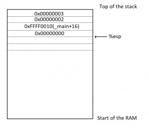
_main:
push 3 # push: CPU指令,将运算子放入stack,即3写入main这个frame
push 2 # push会将ESP寄存器中地址减4
call _add_a_and_b # call:调用函数
add %esp, 8
ret
从_main开始执行,在stack上为main建立一个frame(帧),stack所指向的地址写入ESP寄存器。数据若要写入main这个frame,则写在ESP寄存器所保存的地址。stack:从高位向地位发展。ESP中地址减去四个字节(int)后,新地址写入ESP
Chapter 3
Function
program stored in memory , instructions represented in binary, like data. Each instruction is stored as a word in PC, so 0:0, 4:100, 8: 1000, all the instruction will be ended with 2’b0.
program counter
(PC) (instruction address register)
- address of the instruction is sotred in PC
- 32 bits register
- a special register in CPU (not same as the registers in register file)
function calling
Similarly, in the execution of a procedure, the program must follow these six steps:
- Put parameters in a place where the procedure can access them.
- Transfer control to the procedure.
- Acquire the storage resources needed for the procedure.
- Perform the desired task.
- Put the result value in a place where the calling program can access it.
- Return control to the point of origin, since a procedure can be called from several points in a program.
Function call instructions
-
Function call operation: jump-and-link instruction
jal FunctionLabel(J-type)An instruction that jumps to an address and simultaneously saves the address of the following instruction in a register ($ra in MIPS).
- $ra = PC+4 (the address of following instruction)
- PC = Addr(function label)
-
Function return operation: jump register
jr $ra(R-type)- PC = $ra; Copies $ra to program counter
-
return address
A link to the calling site that allows a procedure to return to the proper address;
in MIPS it is stored in register $ra.
-
caller: The program that instigates a procedure and provides the necessary parameter values.
-
Callee: A procedure that executes a series of stored instructions based on parameters provided by the caller and then returns control to the caller.
-
stack pointer ($sp)
-
pointing to the top of the stack
- By mean top, not mean when adding more items, the address of $sp would not become larger, but it should be subtracion.
-
frame pointer ($fp)
a frame pointer offers a stable base register within a procedure for local memory-references. as $sp might change
leaf function
Eg1: see swap
function that don’t call other functions
addi $sp, $sp, -12 # create spaces in stack
sw $t1, 8($sp) # store data on stack
sw $t0, 4($sp) # actually, no need to operate on $t0 and $t1
sw $s0, 0($sp)
....

lw $s0, 0($sp) # restore data from stack
lw $t0, 4($sp)
lw $t1, 8($sp)
addi $sp, $sp, 12 # destroy spaces on stack
jr $ra # return from function
Non-leaf funciton
Eg2: see sort
function that calls other functions
For nested call, caller need to save on the stack
-
its return address
-
any arguments and temporaries needed after the call
int fact (int n) {
  if (n < 1) return f;
  else return n * fact(n - 1)
}
argument n in $a0, result in $v0
fact:
		addi $sp, $sp, -8
		sw $ra, 4($sp)
		sw $a0, 0($sp)
		slti $t0, $a0, 1
		beq $t0, $zero, L1 # the label tells where to go, such that L1 should have the address
		addi $v0, $zero, 1
		addi $sp, $sp, 8
		jr $ra
L1:
		addi $a0, $a0, -1
		jal fact
		lw $a0, 0($sp)
		lw $ra, 4($sp)
		addi $sp, $sp, 8
		mul $v0, $a0, $v0
		jr $ra
Function Calling Convention
do not follow convention not mean syntax error, but highly likely to create error
when to apply
-
immediatly before the function is called
- pass arguments to $a0 - $a3 (more arguments on stack, addressable via $fp)
- save register that should be saved by caller ( i.e. $a0 - $a3 non-leaf function)
jal
-
in function, but before it starts executing
- allocate memory of frame’s size (moving $sp downwards)
- Save registers that should be saved by the function in the frame, before they are overwritten ($s0-$s7 (if to be used), $fp (if used), $ra (non- leaf function))
- Establish $fp (if desired), $fp = $sp + frame’s size - 4
-
immediatly before the funtion finishes
- if necessary, place the function result to $v0, $v1
- Restore registers saved by the function (pop from frame)
- destroy stack frame (by moving $sp upwards)
jr $ra
Example
When translate from C to assembly language
- Allocate registers to program variables.
- Produce code for the body of the procedure.
- Preserve registers across the procedure invocation.
swap
void swap(int v[], int k) {
	int temp;
	temp = v[k];
  v[k] = v[k+1];
  v[k+1] = temp;
}
1. program argument: `$a0, $a1 -> v, k` temporary variable: `$t0 -> temp`
-
/*procedure body*/
swap: sll $t1, $a1, 2 # $t1 = k * 4
      add $t1, $a0, $t1 # t1 = v + k * 4, the address of v[k]

      lw $t0, 0($t1) # $t1 (temp) = v[k]; load the content in address 0($t1) to the content oof $t0
      lw $t2, 4($t1) # $t2 = v[k+1];

      sw $t2, 0($t1) # v[k] = v[k+1]; store the content in $t2 to thr content in address 0($t1)
      sw $t0, 4($t1) # v[k+1] = temp;
/*procedure return*/
      jr $ra
sort
void sort (int v[], int n) {
  int i, j;
  for (i = 0; i < n; i += 1) {
  	for (j = i – 1; j >= 0 && v[j] > v[j + 1]; j -= 1) {
      swap(v,j);
  	}
  }
}
Problem: sort needs the value in $a0 and $a1, swap need to have the parameters placed in those same registers.
v in $a0, n in $a1, i in $s0, j in $s1
sort:
		addi $sp, $sp, -20
		sw $ra, 16($sp)
		sw $s3, 12($sp)
		sw $s2, 8($sp)
		sw $s1, 4($sp)
		sw $s0, 0($sp)
		add $s2, $a0, $zero	# $s2 = BA of v
		add $s3, $a1, $zero	# s3 = n
		add $s0, $zero, $zero	# i = 0
for1tst:
		slt $t0, $s0, $s3
		beq $t0, $zer0, exit1 # when i >= n, exit the first loop
		addi $s1, $s0, -1 # j = i - 1
for2tst:
		slt $t0, $s1, 0
		bne $t0, $zero, exit2 # when j < 0 exit the second loop
		sll $t1, $s1, 2 # $t1 = j*4
		add $t2, $t1, $s2 # t2: the address of v[j]; v + j * 4
		lw $t3, 0($t2) # v[j]
		lw $t4, 4($t2) # v[j + 1]
		sll $t0, $t4, $t3
		beq $t0, $zero, exit2 # v[j] < v[j + 1]
		add $a0, $s2, $zero # prepare for the paramete needed for next function call swap
		add $a1, $s1, $zero
		jal swap
		addi $s1, $s1, -1
		j for2tst
exit2:
		addi $s0, $s0, 1 #i+=1
		j for1tst
exit1:
	 lw $s0, 0($sp)
	 lw $s1, 4($sp)
	 lw $s2, 8($sp)
	 lw $s3, 12($sp)
	 lw $ra, 16($sp)
	 addi $sp, $sp, 12
	 jr $ra 							# return to calling routine
fib
int fib(int n) {
  if (n < 3)
    return 1;
  else
    return fib(n-1) + fib(n-2);
}
fib:
	addi 	$sp, $sp, -12
	sw		$s0, 8($sp)
	sw 		$a0, 4($sp)
	sw		$ra, 0($sp)
	slti	$t0, $a0, 3
	beq		$t0, $zero, else
	# lw		$ra, 0($sp) unnecessary load here
	# lw		$a0, 4($sp)
	addi	$sp, $sp, 12
	addi	$v0, $zero, 1
	jr		$ra

else:
	lw		$ra, 0($sp)
	lw		$a0, 4($sp)
	addi 	$a0, $a0, -1
	jal	 	fib

	add	 	$s0, $v0, $zero	# we need $s0 to store the value so adjust the stack for 3 items
	sw 		$a0, 4($sp)
	sw		$ra, 0($sp)
	addi 	$a0, $a0, -2
	jal 	fib
	addi 	$t1, $v0, 0
	lw		$ra, 0($sp)
	lw		$a0, 4($sp)
	addi	$sp, $sp, 8
	add		$v0, $t1, $t0
	jr 		$ra
# VE370 2020FA RC Week 3
# Class exercise: fib
# Author: Li Shi

# Important note:
#   This program is written in Linux, and executed by
#     1. spim -bare
#     2. (spim) read "fib.s"
#     3. (spim) run
#   You may need to modify this program to execute in PCSpim.

.text

main:
  addi  $a0,  $0,   8
  jal   fib                 # Call fib(8)
  add   $t0,  $t0,  $0      # Delay
  add   $t0,  $t0,  $0      # Delay
  addi  $a0,  $v0,  0       # Print fib(8)
  addi  $v0,  $0,   1
  syscall
  addi  $v0,  $0,   10      # System call 10 (exit)
  syscall                   # Exit

fib:
  addi  $sp,  $sp,  -12     # Allocate the stack frame
  sw    $ra,  8($sp)
  sw    $a0,  4($sp)
  sw    $s0,  0($sp)        # We will use $s0 later
  slti  $t0,  $a0,  3       # Test for n < 3
  beq   $t0,  $0,   elseBlock
  addi  $v0,  $0,   1       # return 1
  addi  $sp,  $sp,  12
  jr    $ra
  add   $t0,  $t0,  $0      # Delay

elseBlock:
  addi  $a0,  $a0,  -1
  jal   fib                 # fib(n-1)
  add   $t0,  $t0,  $0      # Delay
  add   $t0,  $t0,  $0      # Delay
  addi  $s0,  $v0,  0       # Q: What is $s0 used for?
  addi  $a0,  $a0,  -1
  jal   fib                 # fib(n-2)
  add   $t0,  $t0,  $0      # Delay
  add   $t0,  $t0,  $0      # Delay
  add   $v0,  $v0,  $s0     # return fib(n-1)+fib(n-2)
  lw    $s0,  0($sp)
  add   $t0,  $t0,  $0      # Delay
  add   $t0,  $t0,  $0      # Delay
  lw    $a0,  4($sp)
  add   $t0,  $t0,  $0      # Delay
  add   $t0,  $t0,  $0      # Delay
  lw    $ra,  8($sp)
  add   $t0,  $t0,  $0      # Delay
  add   $t0,  $t0,  $0      # Delay
  addi  $sp,  $sp,  12      # Pop the stack
  add   $t0,  $t0,  $0      # Delay
  add   $t0,  $t0,  $0      # Delay
  jr    $ra
  add   $t0,  $t0,  $0      # Delay
Template
- if ($s0 < $s1) { ... } else { ... }
      slt $t0, $s0, $s1
      beq $t0, $zero, else
      ....
      j elseExit ## remember to jump out when finish if
else: ....
elseExit:
- for ($t0 = 0; $t0 < $a1; $t0++) { ... }
Loop:
		add $t0, $zero, $zero
		slt $t1, $t0, $a1
		beq $t1, $zero, exit
		...
		addi $t0, $t0, 1
		j Loop
exit:
Translation and Startup
Complier
tansform the C program into an assembly language program (a symbolic form of waht the machine understands)
assembler
To produce the binary version of each instruction in the assembly language program, the assembler must determine the addresses corresponding to all labels. Assemblers keep track of labels used in branches and data transfer instructions in a symbol table. As you might expect, the table contains pairs of symbols and addresses.
producing an object module
Example
- In the object file:
the instructions in assembly language just to make the example understandable; in reality, the instructions would be numbers.
Note that the address and symbols that must be updated in the link process is higlighted:
			1. the instructions that refer to the address of procedures $A$ and $B$

			2. the instructions that refers to the data word $X$ and $Y$
linker
Also called link editor. A systems program that combines independently assembled machine language programs and resolves all undefined labels into an executable file.
-
merge segments
-
resolve labels (determine their address)
-
patch location-dependent and external reference
example of linked objects
Object is already machine language, but no memory has been traslated (the translator do not know about)
the text segment starts at address 40 0000hex and the data segment at 1000 0000hex.
- The jals are easy because they use pseudodirect addressing. The jal at address 40 0004hex gets 40 0100hex (the address of procedure B) in its address field, and the jal at 40 0104hex gets 40 0000hex (the address of procedure A) in its address field.
- The load and store addresses are harder because they are relative to a base register. This example uses the global pointer as the base register. Figure 2.13 shows that $gp is initialized to 1000 8000hex. To get the address 1000 0000hex (the address of word X), we place 8000hex in the address field of lw at address 40 0000hex (Because it is 2’s complement). Similarly, we place 7980hex in the address field of sw at address 40 0100hex to get the address 1000 0020hex (the address of word Y).
- also output an object file
Loader
- Reads the executable file header to determine size of the text and data segments.
- Creates an address space large enough for the text and data.
- Copies the instructions and data from the executable file into memory.
- Copies the parameters (if any) to the main program onto the stack.
- Initializes the machine registers and sets the stack pointer to the first free location. ($sp, $gp, $fp)
- Jumps to a start-up routine.
- copies the parameters into the argument registers ($a0...) and calls the main routine
- When the main routine returns, the start-up routine terminates the program with an exit system call
之前讲了static link, 即before the program is run 1. the library routines become part of the executable file 2. it loads all routines in the library that are called anywhere executable
so -> dynamically linked libraries (DLLs): Library routines that are linked to a program during execution.
Dynamic Linking
dll: dynamic linking library
Topic 4
Instructoin coding, how the assembler and linker transform into machine code.
MIPS instruction -> 32 bits words, translated into binary information (machine code)
first 6 bits -> opcode always, for all three types. Based on this, CPU now what to do.
R-format
totally 32 bits, can see from the reference card 
Instruction fields
Here is the meaning of each name of the fields in MIPS instructions:
- op: Basic operation of the instruction, traditionally called the opcode.
- rs: The first register source operand.
- rt: The second register source operand.
- rd: The register destination operand. It gets the result of the operation.
- shamt: Shift amount. (Section 2.6 explains shift instructions and this term; it will not be used until then, and hence the field contains zero in this section.) only use when shift, represents the number we want to shift (0-31)
- funct: Function. This field, often called the function code, selects the specific variant of the operation in the op field.
add $t0, $s1, $s2
add: 0 (opcode)
rs: $s1 (5 -bits store the memory) 10001
rt: $s2 10010
rd: $t0 (becasue this is the register destination)01000
add and sub have the same opcode, use the different func field to distinguish between these two.
I-format
i- immediate number

rt: destination now however it could also be source (determine by read / write operation)
rs: source or base address register
constant / address: to / offset added to base address in rs
Read: source register Write: destination
sw $t0, 4($s0) # $s0->rs / $t0 -> rt
read from the register both $s0->rs $t0->rt. // no destination register needed
relative address = (LOOP-PC-4)/4. // because relative address should have a 32-bits address, so by calculation, we could use relative address (16 bits)
lui $t0, 255 # because $t0 is the destination register
| opcode | rs | rt | Immediate |
|---|---|---|---|
| 001111 | 00000 | 01000 | 0000 0000 1111 1111 |
J-format

encode full address in instruction, use 26 bits represent a 32 bits address
leave the first 4 bits of PC untouched.
Addressing in Branches and Jumps
- J-type: 6 bits for operation field and the rest of the bits for the address field.
j 10000 can be assembled into
| 2 | 10000 |
|---|---|
| 6 bits | 26 bits |
the value of the jump opcode is 2 and the jump address is 10000
- PC-relative addressing
a branch instruction would calculate: Program counter = Register + Branch address
for conditional branches: loops and statements
Decoding Machine Code
- converting hex to binary to find op fields, determine the operation
-
How to get address
- immediate addressing
- I-type
addi $s0, $s1, -1
- I-type
- register addressing
- R-type / I-type : all or some operands provided by register IDs directly
add $t0, $s0, $s1
- R-type / I-type : all or some operands provided by register IDs directly
- base addressing
- I-type: operands provided by using base address of memory location
lw $t0, 32($s0)
- I-type: operands provided by using base address of memory location
- PC-relative addressing
- Operands relative to PC, used for near branch target address = PC + 4 + offest * 4 ,
beq $s0, $s1, LESS
- Operands relative to PC, used for near branch target address = PC + 4 + offest * 4 ,
- Pseudodirect addressing
- encode full address in instruction J-type (
jandjal) target address = PC[31:28] : address * 4
- encode full address in instruction J-type (
- immediate addressing
instructions from memory & data from/into RF/memory
T05
Review of Digital Logic
who to control reading / writing? do not read / write at the same time -> control signal in RF
-
memory (access memory is slower than access RF, because of the big circuit of memory, need to decode the address)
- SRAM (Static RAM)
- DRAM
memory in MIPS
insturction memory: only read afterwards
data memory: only one address for read / write
If need write, write first
T06
Single Cycle Processor Chapter 4.1-4.4
■■ The memory-reference instructions load word (lw) and store word (sw)
■■ The arithmetic-logical instructions add, sub, AND, OR, and slt
■■ The instructions branch equal (beq) and jump (j), which we add last
PC is controled by clock signal
every instruction, needs: send the PC to the memory that contains the code and fetch the instruction from that memory / read one or two registers, using fields of the instruction to select.
state element: a memory element, such as a register or a memory
- clocking methodology: edge-triggered clocking: a clocking scheme in which ass state changes occur on a clock edge. Only state elements can store data value, any collection of combinational logic must have its inputs come from a set of state elements and its outputs written into a set of state elements. The inputs are values that were written in a previous clock cycle, while the outputs are values that can be used in a following clock cycle.
- ALUOp & funct -> ALU Control
Generate a 2-bit ALUOp (by CPI controller). With ALUOp and funct field -> ALU control
that is, using multiple levels of decoding -> reduce the size of the main control unit (opcode before)
The corresponding truth table is as follows, don’t care term all represented with X
-
instruction format
opcodebits [31:26] as Op[5:0]Two register be read
rsrt[25:21] and [20:16] (R-type, beq, store)base register for load and store
rs[25:21]offset [15:0] (beq, load, store)
destination register - load:
rt[20:16] - R-type:
rd[15:11] -> use a Mux to select -
usage of seven control lines
For R-type, will not use data memory
lw: read register from register file, ALU calculate the address, read data from data memory, store the data read back to register file

Clocking Methodology
lw load type instruction will need most time (becasuse of read from data)
beq only read from register and do some calculation, will not cost more time
sigle-cycle processor is not feasible to vary period for differerent instructions

clock cycle time for single-cycle processor will be 800ps, regardless of the instructions’ distribution
execution time is
multi-cycle CPU - FSM: each instruction takes multiple cycles to execute
still which operation will take the longest time - Instr Fetch: 200ps
However, with different distribution, multi-cycle will have different total execution time, some may be worse than single-cycle some may be worse.
T07
Pipelined Processor
divide the big combinational circuit into five small stages, one step per stage per cycle
- IF: Instruction fetch
- ID: Instruction decode and register file read
- EX: Execution or address calculation
- MEM: Data memory access
- WB: Write result back to register
Single-clock-cycle diagram / multi-clock-cycle diagram
Instruction-level parallism: multiple instructions exectued at the same time
execution time for each instruction does not improve (all need to execute the five stages)
T08
Data Hazards
- add stalls: nop instructions
- forwarding (bypassing) : use data before it is stored into the register
hazard notation
1a. EX/MEM.RegisterRd = ID/EX.RegisterRs
1b. EX/MEM.RegisterRd = ID/EX.RegisterRt
2a. MEM/WB.RegisterRd = ID/EX.RegisterRs
2b. MEM/WB.RegisterRd = ID/EX.RegisterRt
-
Forwarding in EX stage
we consider only the challenge of forwarding to an operation in the EX stage, which may be either an ALU operation or an effective address calculation. (instruction tries to use a register in its EX stage that an earlier instruction intends to write in its WB stage, we actually need the values as inputs to the ALU. )
EX hazard
if (EX/MEM.RegWrite  // check whether previous a WB to register file needed
 and (EX/MEM.RegisterRd ≠ 0)  // check whether we need to change the content of $zero
 and (EX/MEM.RegisterRd = ID/EX.RegisterRs)) // check whether the destination register need to use for this ALU
 ForwardA = 10

if (EX/MEM.RegWrite
 and (EX/MEM.RegisterRd ≠ 0)
 and (EX/MEM.RegisterRd = ID/EX.RegisterRt)) ForwardB = 10
Note that the EX/MEM.RegisterRd field is the register destination for either an ALU instruction (which comes from the Rd field of the instruction) or a load (which comes from the Rt field).
MEM HARZARD
if (MEM/WB.RegWrite
	and (MEM/WB.RegisterRd ≠ 0)
	and not(EX/MEM.RegWrite and (EX/MEM.RegisterRd ≠ 0))
			and (EX/MEM.RegisterRd ≠ ID/EX.RegisterRs)
	and (MEM/WB.RegisterRd = ID/EX.RegisterRs)) ForwardA = 01

if (MEM/WB.RegWrite
	and (MEM/WB.RegisterRd ≠ 0)
	and not(EX/MEM.RegWrite and (EX/MEM.RegisterRd ≠ 0))
		and (EX/MEM.RegisterRd ≠ ID/EX.RegisterRt)
	and (MEM/WB.RegisterRd = ID/EX.RegisterRt)) ForwardB = 01
To select the signed immidiate, add another MUX unit (choose from the output of forward B between signExtend)
Load use hazard detection
If value not computed when needed
$2 is needed in and instruction before it is read from data mem
*
Add the stall(bubble) by
- Force control signals in ID/EX register to 0’s (the MUX) (nothing will do with this 0 control signals)
- Prevent the update of PC and IF/ID register
PCWrite=0, IF/IDWrite=0 when Hazard=1
Final Review
Pipeline
hazard detection unit and forwarding unit are seperate, such that we should not let hazard detection to control whether and which should forwrding
-
load-use hazard. insert bubbles: let control signals in ID/EX registers be zero, EX, MEM, WB stage will do nothing with these zero control signals. Registers value still exist. PC and IF/ID register’s value do not change. 会有EX的data hazard(对nop),但是ineffective,会在下一个MEM hazard的作为下个instruction的值替换
在下一个instruction为sw时,如有data hazard,为避免stall太多,加一个MemSrc来控制data mem要write的data可以直接来自MEM/WB
-
control hazard, flush the wrong instruction. When determine branch (including address calculation and whether to branch through comparator) in
- ID: IF/ID.Reg.flush
- EX: IF/ID.Reg.flush + ID.flush
- MEM: IF/ID.Reg.flush + ID.flush + EX.flush
ID.flush 和 EX.flush 是针对control signal而不是整个register都变为0
-
data hazard for branch 前一个是R type 必须stall 一个,前一个是lw必须stall 两个。再进行forwarding 到ID ex
-
exception
Cache
All data in a memory must also be present in its lower level
Overall
-
Block placement
-
block identification
- for direct map: 通过block index locate,tag只需要比对一次(index是block index)
- for n-way set associative: 通过set index locate,比较所有tag,n次(无block index 只有set index)
- for full associative:search all entries(n times) / lookup table (0 time) (无block/set index)
-
block replacement
-
write strategy
write through 比起 write back 要cheaper一些,因为check match和write data可以同时进行(saves a step for hit)
以及可以分别被应用于两个的 write allocation on miss
write allocate: allocate cache block on miss by fetching corresponding memory block; update cache block; update memory block
no write allocate: write around(write directly to memory); fetch from memory
- write through 要找到原有的先写到cache里面,再用新的覆盖掉cache里面的然后写入main memory
- write buffer: 针对write through的方法,把要写进memory的data放进buffer里面,CPU接着往下走留着buffer完成之后的工作(cache里面的和buffer一起实时更新,main里面的memory在之后由buffer更新)
- write back: keep a dirty bit. When need to replace a block with dirty bit == 1 in the cache, write the block back into main memory first
- write buffer:用于write back则是write into buffer and checking match 同时
- write through 要找到原有的先写到cache里面,再用新的覆盖掉cache里面的然后写入main memory
-
Sources of misses 3C model: Compulsory | Capacity | Conflict
Points
-
principle of locality
-
principle of memory access
- Hit time: time to access a memory, including
- whether hit/miss
- time to pass block to requestor
- miss penalty: time to fetch a block from lower level upon a miss, including
- time to access the block
- time to transfer it between levels
- time to overwrite the higher level block
- time to pass block to requestor
- Hit time: time to access a memory, including
-
block size
- larger block should reduce miss rate (spatial locality)
Difference types of cache
word offset 是针对一个block里面的word数量决定
并不是改了cache内容就dirty了!是一个block里面的数被sw/sb改掉了
all blocks in a set must be searched (tag search in parallel + extra hardware & access (hit) time )
directed mapped cache:
- byte address = word address (block address(tag + block index) + word offset) + byte offset
- cache consists of (valid bit + tag + data)
word offset由一个block里面有多少word决定 (但transfer要一个block一起transfer,于是会有hit due to spatial locality)可以用除法来表示舍弃之后几位(除以4就是舍掉最后两位,比如offset)
、
N-way set associative cache: 需要set index,但access一个set中的block必须compare N次
byte address = word address (block address(tag + set index) + word offset) + byte offset
Full-associative cache
一个block可以去任意一个cache entry,comparator的数量就是cache size, no index
-
byte address = word address (block address(tag) + word offset) + byte offset
-
Average Memory Access Time (AMAT): hit time + miss rate * miss penalty
-
reduce miss penalty: early start / critical word first 可能要再看
-
increase associativity decrease miss rate (with diminishing improvement)
-
multiple caches时的
-
LRU 要keep reference bit 对于high associativity: complex and costly hardware
Virtual Memory
-
VM block is called a page, VM miss is called a page fault
-
virtual address some maps to physical address, some to disk address, through address translation
-
physical address usually smaller than virtual address
-
n to one map
-
page fault: page is not present in memory, the page must be fetched from disk
-
-
virtual address = virtual page number + page offset
- Processor always provide virtual address
- page offset: eg. 12bits -> 4K byte page size
- virtual page numebr translated into physical page number, while physical always be larger
- virtual page number used as tag when TLB hit & used as page table index when TLB miss to access page table
-
Translator - Page Table (for each program)
- Store all mapping & indexed by virtual page numbers & located in main
- page table register
-
Translation Look-aside Buffer (TLB) - fast cache of page table within CPU
- Page table -> TLB == main -> cache
- a subset of page table
- full associativity: to lower miss rate (because for small TLB, access time not a major concern)
- LRU (need to keep a reference bit) or random replacement
- physical address will be pointed by both TLB and page table
-
TLB miss: cache tag (comparison) + valid bit | Page Fault: by page table valid bit (no comparison)
- TLB miss:
- TLB is full: ref bit and dirty bit of replaced entry should be copied back to page table, but not for valid bit
- TLB miss:
-
Page write: disk write takes millions of time ! 不可以write through
- page table always write back ! (dirty bit in page table)
- write an entire page is more efficient than write a word
-
TLB and cache interaction:还要再看
- for physically addressed cache
- Virtual addr -> TLB -> provide physical address to cache (may have longer time because TLB on critical path)
- The cache is physical address, (cache index and tag are both physical )
- virtually addressed cache: 只有在cache miss的时候需要将virtual address翻译成physical address
- complications due to aliasing
- This ambiguity would allow one program to write the data without the other program being aware that the data had changed. Completely virtually addressed caches either introduce design limitations on the cache and TLB to reduce aliases or require the operating system, and possibly the user, to take steps to ensure that aliases do not occur.
- for physically addressed cache
Overall Framework
conflict miss Also called collision miss. A cache miss that occurs in a setassociative or direct mapped cache when multiple blocks compete for the same set and that are eliminated in a fully associative cache of the same size. not exist for full-associativity cache
再看一下书上的判断题/可能的多选题/page table那几个书上的题